
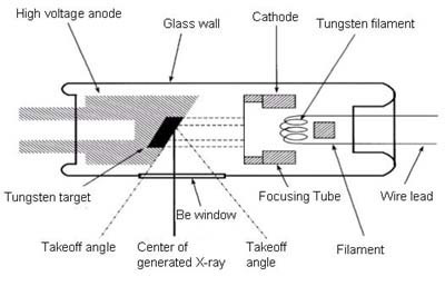
The simplest and most common type of x-ray generator is based on the x-ray tube. A tube source contains a filament in which electrons are released through thermionic emission. Electrons released from the filament are accelerated by an electric field and directed onto a metal target embedded in the anode.
X-rays are generated as the electrons are decelerated and absorbed in the target. They are released from the tube through a window, which is typically made from beryllium, which is largely transparent to x-rays because of its small number of electrons (Z=3). The whole tube is evacuated in order to prevent electrical discharges and to avoid electrons being scattered and x-rays absorbed inside the tube.
The choice of anode material determines the energy of the x-rays produced by the tube. Common target materials are copper for most diffraction experiments, molybdenum or silver for scattering experiments requiring higher energies, and tungsten in medical x-ray machines, where much higher energies are needed in order to penetrate several centimetres of flesh and bones.
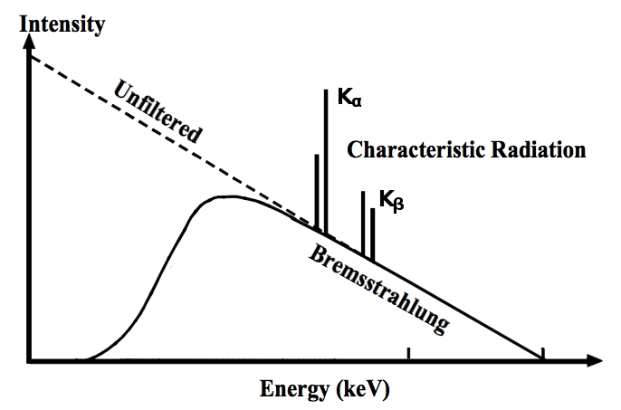
The radiation from an x-ray tube has a broad background spectrum which decreases gradually up to a limit. This is known as Bremsstrahlung (German for braking radiation) and is caused by the fact that a moving charged particle, when entering matter, will decelerate by interaction with the charges present in the target material. The energy lost in this process is released as a photon. The cut-off energy is determined by the accelerating voltage, i.e. the kinetic energy of the electron before impact on the target.
In addition to the Bremsstrahlung, there are characteristic lines at particular energies which depend on the chemical element of which the anode is made. These correspond to transitions between different levels in the electronic structure of the target atom. Since scattering experiments typically use monochromatic radiation, these characteristic lines are used, with as much of the Bremsstrahlung filtered out as possible.
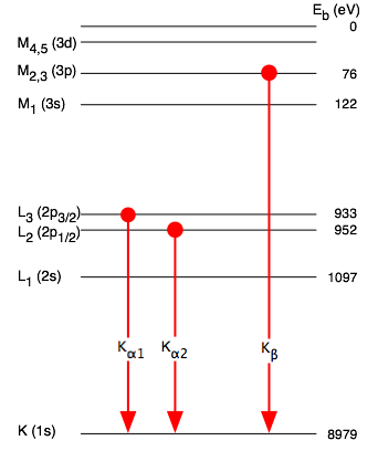
The diagram shows the transitions giving rise to the characteristic lines of an x-ray emission spectrum. The energies shown relate to the electronic structure of copper, the most common anode material used in diffractometers. The strongest emission lines result from transitions of electrons of outer levels into an unoccupied state closest to the nucleus, the 1s level, after an electron has been removed from there due to interaction with an accelerated electron coming from the cathode of the x-ray tube. According to the quantum-mechanical selection rules for such transitions, the angular momentum has to change by a prescribed amount, which means that only transitions from p-states are allowed. The possible transitions in the copper atom are therefore the $\mathrm{K_{\alpha}}$ lines from the two energetically slightly different 2p levels and the $\mathrm{K_{\beta}}$ line from the next level up (3p). The symbol for these transitions consists of a capital letter representing the main quantum number $$\mathrm{K,L,M}\dots\textrm{ for }n=1,2,3\dots$$ of the final state of the transition and a subscript denoting the number of increments by which the main quantum number changes $$\alpha,\beta,\gamma\dots\textrm{ for }\Delta n=1,2,3\dots\quad.$$ Since we typically need monochromatic radiation, the $\mathrm{K_{\beta}}$ and higher lines are typically filtered out using the absorption edge of a neighbouring element in the periodic table. The two $\mathrm{K_{\alpha}}$ lines cannot be separated, but their relative intensity is known, and diffractograms can be corrected for this unavoidable dichromatism.
Increasing the current of the cathode in principle increases the x-ray output of the tube linearly. However, the thermal load on the target limits the extent to which the current can be increased. To overcome this, rotating anodes have been developed, where the target rotates in such a way that only part of it is exposed to the electron beam at any one time. This gives each spot of the anode a duty cycle during which heat can be dissipated, avoiding melting the target. Another engineering solution is the use of liquid-jet anodes, where the x-rays are generated from a rapidly pumped liquid target which can be cooled more effectively. These improvements increase the x-ray output of tube generators several times.
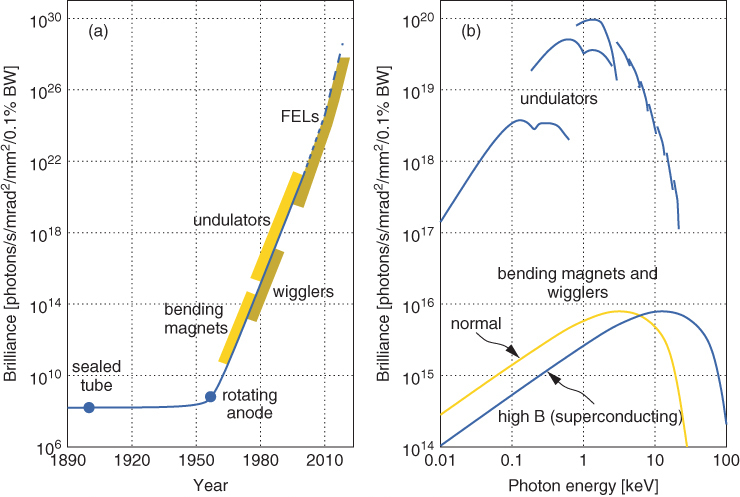
Orders-of-magnitude increases in x-ray flux can be achieved by synchrotron sources, albeit at the price of having to go to a central facility to do an experiment. Technological developments at synchrotrons such as insertion devices have increased the output of the x-ray source by over twenty orders of magnitude compared to what can be achieved with a laboratory (tube) source, allowing time resolved experiments, experiments using coherent x-rays, as well as experiments with variable x-ray energy. The output of x-ray sources is usually compared in terms of their brilliance: photons per time, solid angle, cross section and energy bandwidth.
At a synchrotron source, electrons are emitted from an electron gun in the same way they are generated in the cathode of an x-ray tube. They are then accelerated by an electric field in a linear accelerator and subsequently injected into the synchrotron as such. This is a circular accelerator, where a beam of electrons is kept on a closed loop and accelerated to relativistic speeds by gradually ramping up the magnetic field keeping the particles on their trajectory as they speed up. Once at the target speed, the electrons are transferred in bunches into the storage ring, where they are kept at a constant speed on a constant circular trajectory (with a larger radius of curvature than in the accelerator synchrotron).
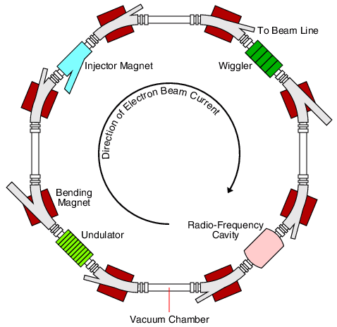
The figure shows a schematic of the components of a storage ring: The injector is the point where the electrons are transferred from the synchrotron accelerator located on the inside of the storage ring. It is a magnet which is switched on to bring the newly arriving electron bunches onto the trajectory of the main storage ring. Until recently, this required dropping the existing ring current and filling the ring with fresh bunches, but it is now possible to switch the injector magnet rapidly to deflect fresh bunches into the ring path while allowing existing bunches to pass through without deflection. The ring current is kept on a closed loop by placing bending magnets in the corners of a polygon. In each bending magnet, the magnetic field causes charged particles to be deflected at right angles to both the field and their direction of travel (right-hand rule). As the change of direction is a form of acceleration (change of the velocity vector in direction if not in magnitude), the charged particle will radiate. This is the point at which the x-rays are produced in a synchrotron source. X-ray beamlines are attached to the bending magnets to capture the x-rays and use them for experiments. Because the electron bunches lose energy in this process and would therefore gradually spiral into the inside of the electron beam tube of the storage ring, there is at least one radio-frequency cavity in the ring where the electrons are pushed forward by a high-frequency magnetic field. This also re-focuses the electron bunches by braking fast electrons and accelerating slower ones to a mean energy.
Early synchrotrons were built as particle-physics instruments, and the x-rays generated at the bending magnets were used 'parasitically' for scattering experiments, initially mostly in solid-state physics. As x-ray scattering and spectroscopy became more widely used in materials science, chemistry, biology and allied disciplines, synchrotron storage rings began to be built as dedicated x-ray sources in the early 1980s. To maximise their utility, the straight sections of the polygonal storage ring between the bending magnets were fitted out with insertion devices, where the electron beam is forced onto zig-zag paths by spatially alternating static magnetic fields, producing more x-rays as they wiggle around their general trajectory around the ring.
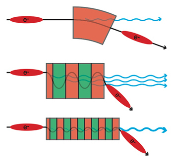
The Figure compares the electron trajectory and x-rays generated in a bending magnet with the situation in the two types of insertion devices, wigglers and undulators. The difference between the two is the strength of the magnetic field, $B$, and the distance $\lambda_u$ between magnets of opposite polarity. Together, these differences are reflected in the undulator parameter, $$K=\frac{eB\lambda_u}{2\pi m_ec}\qquad,$$ where the other symbols have their usual meanings as fundamental constants. For a wiggler, $K\gg 1$, there are a small number of relatively strong magnets, while in an undulator, $K\ll1$, a larger number of smaller magnets are used. In both limits, the number of photons is greatly increased compared to a bending magnet because the electrons are forced to carry out a much larger number of changes of direction. The difference is in the shape of the x-ray spectrum produced by the two devices.
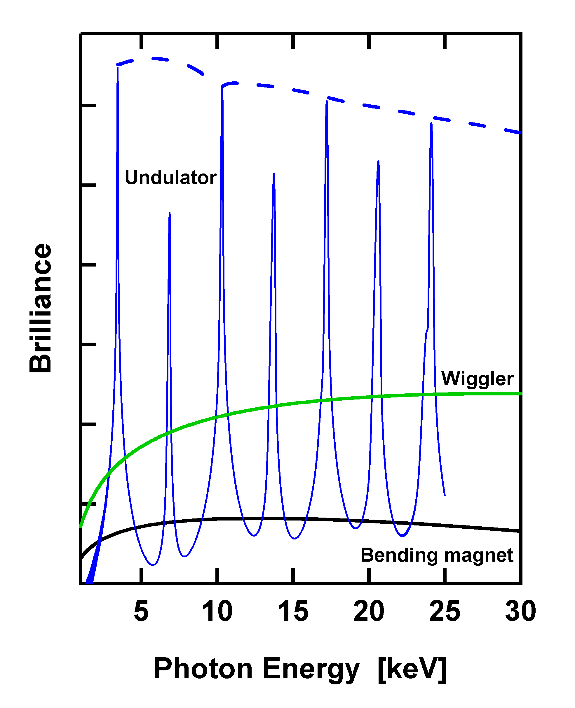
In a wiggler, the same process that generates x-rays in a bending magnet simply takes place on a larger scale, with multiple turns of the electron trajectory on a short distance, causing a larger x-ray flux with a smooth variation with energy. The undulator spectrum, on the other hand, has sharp resonances at regular energy intervals, where the emissions at every magnet of the undulator are in phase. Since the magnet spacing $\lambda_u$ is fixed when the undulator is assembled, the position of the resonances in the spectrum can be adjusted via the magnetic field; in practice this is done by changing the undulator gap, the spacing between the poles of each magnet. Apart from increasing the brilliance of the source by several orders of magnitude when one of the resonances is used, the resonant photons are also coherent, allowing experiments that explore phase relationships before and after interaction with a sample.
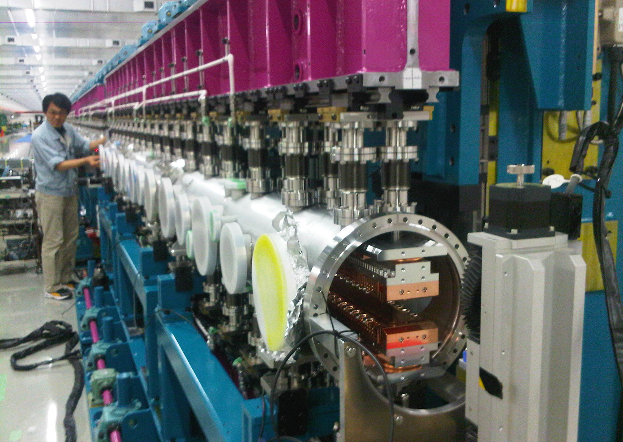
The length of an undulator in a storage ring is limited by the length of a straight section between two bending magnets. However, if built into a linear accelerator, an undulator can be made arbitrarily long. This has led to the concept of the free electron laser (FEL) as a very bright source of coherent x-rays. The photo shows the X-FEL undulator at the SACLA facility in Japan during assembly. The series of alternating magnets can be seen inside the vacuum vessel. In an FEL, the photon field is built up to such a strength that stimulated emission occurs, producing another increase in x-ray output by several orders of magnitude. This enables experiments on a femtosecond timescale, where snapshots of transient states e.g. during chemical reactions can be observed by scattering or spectroscopic techniques.
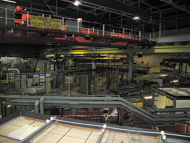
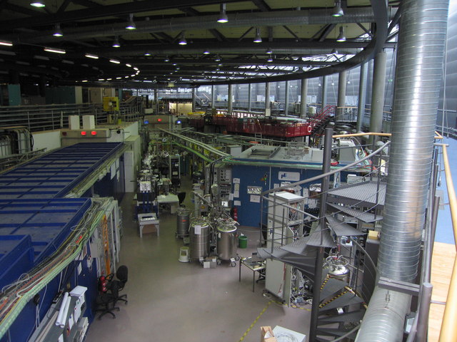
The first photograph shows the interior of the (now defunct) Synchrotron Radiation Source (SRS), Daresbury near Warrington. This was the first synchrotron specifically built as an x-ray source and was opened in 1981. The curvature of the storage ring can be seen across the roof of one of the beamline hutches. The second photo shows the experimental hall at Bessy-II, Berlin, which opened in 1998. Here, two beamlines can be seen emerging from the storage ring, which is inside the white beam tunnel on the left of the photo. The left beamline uses high-energy x-rays for scattering experiments and is therefore enclosed in a lead hutch (the blue building on the left). The beamline on the right uses less energetic x-rays for spectroscopic experiments, which can be contained in steel vacuum tubes.
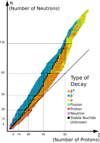
There is no direct neutron equivalent of an x-ray tube; the only laboratory-scale neutron source that could be used is a radioactive source which produces neutrons as a result of a natural fission reaction. As the nuclide chart shows, suitable nuclei are few and far between - most decay either by turning a neutron into a proton or the other way round in order to get closer to the line of stability, emitting either a positron ($\beta^+$) or an electron ($\beta^-$) in the process. The only neutron emitters are neutron-rich isotopes of very light elements, or very heavy nuclides decaying by spontaneous fission reactions. This means that naturally decaying radioactive samples are of little use as neutron sources for scattering experiments.
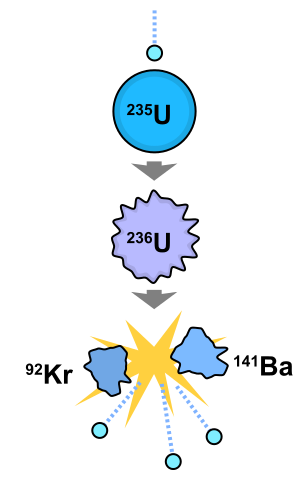
A better bet is a stimulated fission reaction following neutron capture. A typical reaction is that of $\mathrm{^{235}U}$ under neutron irradiation, which is commonly used in reactor sources as well as nuclear power stations. This produces a $\mathrm{^{236}U}$ nucleus in an excited state due to the kinetic energy of the captured neutron, which will split into two fragments, e.g. $\mathrm{^{92}Kr}$ and $\mathrm{^{141}Ba}$, although other combinations occur as well. In addition to these product nuclei, more neutrons are released (three in this case as can be seen from the difference in the mass numbers of the nuclei before and after the reaction), and some of these neutrons will propagate the chain reaction in the reactor. Other neutrons will leave the reactor, and some of them can be fed into beam tubes leading to neutron experiments surrounding the reactor. In order to keep the reaction going, the number of neutrons generated has to be equal to the number of neutrons consumed in the reaction plus those lost to the surroundings. This is known as the criticality condition. The difference between a research reactor and a nuclear power station (apart from the scale) is that a research reactor is optimised to produce a large number of excess neutrons but as little heat as possible, whereas a power station keeps the neutron loss small while generating a lot of heat that can be used to operate steam generators.
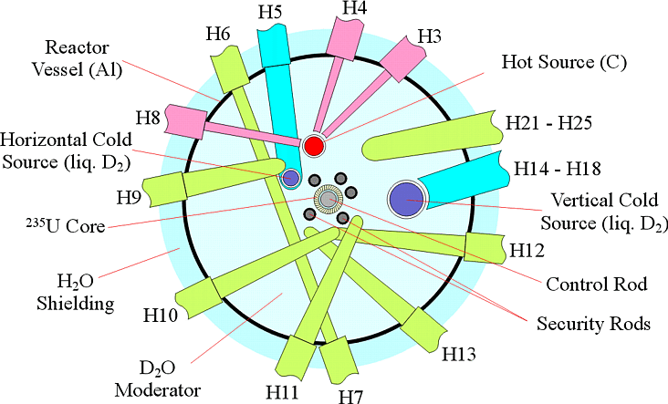
The diagram shows the layout of the High-Flux Reactor (HFR), Institut Laue-Langevin (ILL), Grenoble, a joint European research facility for neutron experiments. The reactor core sits at the centre of the reactor vessel, surrounded by control rods made from a boron-containing neutron absorber material, which are used to keep the criticality ratio at precisely one. There are also safety rods which can be dropped into the reactor to shut down the reaction immediately. Since there are several nuclear reactions taking place simultaneously, each producing several neutrons with different kinetic energy, the spectrum of the neutrons generated in the reactor is quite broad, and many of the neutrons are too fast (energetic) to be useful for scattering experiments - they wouldn't interact with a sample at all. Therefore, the reactor vessel is filled with heavy water ($\mathrm{D_2O}$) as a moderator, i.e. the fast neutrons scatter repeatedly with heavy water molecules until their velocity distribution corresponds to the temperature of the (thermostatised) water. Such thermal neutrons have a median energy which corresponds to a wavelength more suitable to resolving atomic structures, and the energy distribution is well known as it is given by the Maxwell distribution of velocities. For some experiments, cold neutrons are more suitable, which have been thermalised with liquid heavy hydrogen ($\mathrm{D_2}$) located in cold sources embedded in the reactor vessel instead. These have walls that are thermally insulated against the heavy water of the reactor vessel but are transparent to fast neutrons which are captured and subsequently thermalised in the cold source. Similarly, graphite can be used as a hot source to thermalise fast neutrons at a temperature above ambient. Beamlines leading to the various experiments begin at various points within the reactor vessel or at a cold source. The reactor and the beamlines are surrounded by shielding. Since protons are good neutron absorbers, a tank containing normal water ($\mathrm{H_2O}$) surrounds the reactor vessel, and the whole structure is covered in lead-infused paraffin (to shield x-rays as well as neutrons).
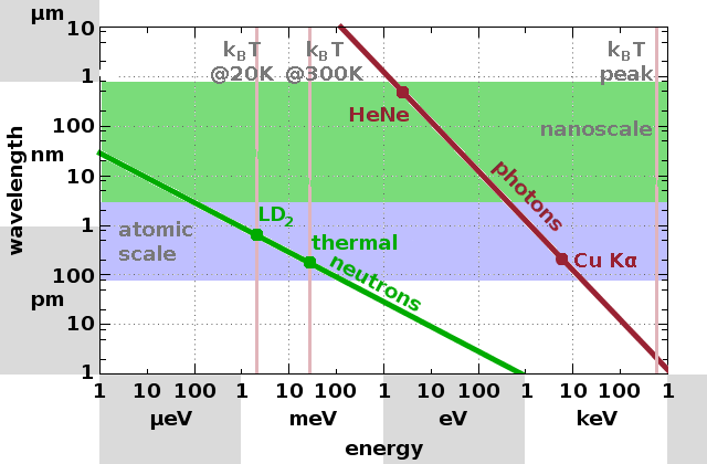
The wavelength-energy diagram illustrates the properties of beams produced by different sources. $\mathrm{Cu\,K_{\alpha}}$ radiation as well as the median of the velocity distributions of both thermal and cold neutrons have wavelengths comparable with the length scale of chemical bonds. Therefore, they can be used for diffraction experiments or for diffuse scattering experiments on the nano-scale. The peak of the (non-thermal) distribution of fast neutrons from fission reactions after neutron capture is shown on the right. The wavelength of such neutrons is several order of magnitude shorter than atomic distances. Therefore, these neutrons aren't suitable for scattering experiments. The wavelength of a HeNe laser (633nm, red light) is also shown for comparison. Such light can be used for diffraction experiments on periodic structures of the order of several hundred nanometres, e.g. layers in polymer films, or for diffuse scattering (static light scattering, SLS) experiments on structures of several microns in size.
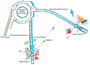
An alternative to a reactor-based neutron source is a spallation source. Here, a heavy-element target such as tantalum is subject to proton irradiation, causing a fission reaction which releases neutrons. Unlike a reactor source, there is no chain reaction and no criticality condition. Instead, proton pulses are generated from a hydrogen plasma, accelerated first in a linear accelerator and then in a synchrotron, after which they are directed towards the target. Because of the pulse structure of the source, the neutron emission is also pulsed, which makes experiments investigating time correlations on the scale of the pulse rate more straightforward than with a continuous (reactor) source. A spallation source also has the advantage that it can be switched on and off more easily and that less material is radiologically activated, reducing radioactive waste. The diagram shows the layout of the Isis spallation source at the Rutherford-Appleton Lab, Didcot, with its proton synchrotron and two target stations surrounded by neutron (and muon) beamlines.
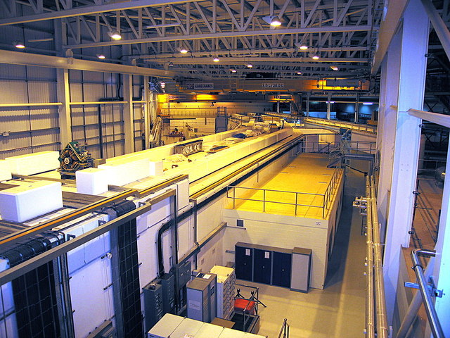
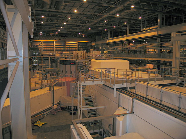
The photos (both taken from the same spot) show the proton beam tunnel coming from the proton synchrotron on the right and continuing to the second target station on the left. The target is located inside the bluish circular structure in the left photo. Neutron beamlines can be seen emerging from the target station. It is evident that the amount of shielding and the scale of the installation is considerably larger than what is needed at an x-ray source because of the need to contain fast neutrons as well as activated materials.
Having established where the x-rays and neutrons for scattering experiments come from, we will now look at a number of scattering experiments beyond diffraction of perfect crystals, including diffuse and total scattering, and their applications in different areas of materials science. To start with, we'll be looking at the effect of disorder in solid structures.