
The strength of materials under external forces depends on their defect structure as well as their ideal crystal structure. In particular, dislocations affect the mechanisms by which a material responds to stresses and ultimately fails.
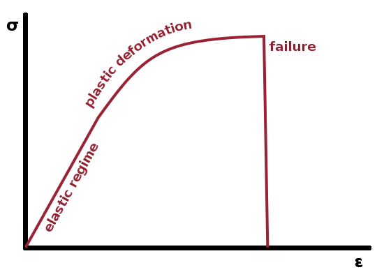
The figure shows schematically the relationship between stress, $\sigma$, in $\mathrm{N\,m^{-2}}$, which is the force acting on a crystal structure normalised to the cross sectional area on which it is acting. Therefore, the units of stress are the same as those of pressure; however, unlike pressure, stresses always have a direction along which they act. Since a stress causes a distortion of the atomic potential landscape, it will result in a change of atomic distances along the direction of the stress. The relative change in length which results is known as strain, $\epsilon=\frac{\Delta l}{l_0}$, and is measured in %.
As long as stresses are small, they only lead to elastic deformation, i.e. the strain will cease as soon as the stress is removed. In this case, Hooke's law, $\Delta l\propto F$, applies, and stress and strain are proportional to each other: $$\sigma=E\epsilon\qquad.$$ The constant of proportionality is the Young's modulus, $E$, also known as the elastic modulus or elastic constant.
If the force acting on the material is a torsional force, the stress caused in the plane perpendicular to the torsional axis is a shear stress, $\tau$, causing a shear strain, $\gamma$. Again, in the elastic case, the two are proportional, $$\tau=G\gamma\qquad,$$ with the shear modulus, $G$, as the constant of proportionality. Finally, in an isotropic medium, the bulk modulus, $K$, links the pressure to a relative volume change in a similar way: $$p_{\textrm{hyd}}=K\frac{\Delta V}{V}\qquad.$$
Beyond the elastic regime, plastic deformation will take place, i.e. the strain grows more than proportionally with the stress applied, and the deformation caused will be persistent because irreversible changes are made to the structure of the material. This ultimately leads to failure.
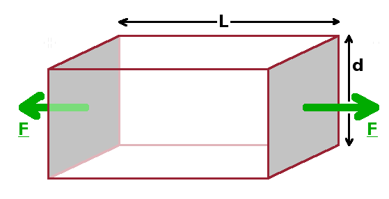
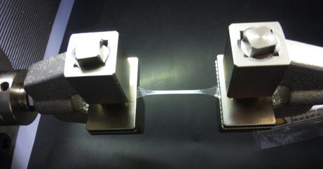
The tensile test is a standardised materials testing method, where a specimen is mounted between two identical clamps, and both clamps are pulled apart with equal forces applied at both ends of the specimen. Most materials exhibit necking under these conditions, i.e. the stress applied leads simultaneously to an elongation, $\epsilon_{\parallel}=\frac{\Delta l}{l_0}$, along the tensile axis and a contraction, $\epsilon_{\perp}=-\frac{\Delta d}{d_0}$ along the two directions perpendicular to it. Poisson's ratio, $\nu=-\frac{\epsilon_{\parallel}}{\epsilon_{\perp}}$, quantifies the extent to which the material thins while being stretched. Since the contraction occurs in the plane perpendicular to the tensile axis, where shear stresses also occur, the Poisson ratio links the Young's and shear moduli: $$E=2G(1+\nu)=3K(1-2\nu)\qquad.$$ In an isotropic medium it also allows to calculate the bulk modulus.
While most materials behave in this way under tensile load and thus have a positive Poisson ratio, there is a small class of materials which expand laterally under tensile stress, i.e. have a negative Poisson ratio. These are known as auxetics, and their peculiar behaviour arises from cross links in the structure which redirect tensile stresses at right angles by increasing internal free volume.
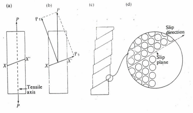
The simplest mechanism by which a material can respond to a tensile stress is block slip. Here sections of crystal slip at angle with the tensile axis along a specific lattice plane where the crystal structure is weakest. As a result, the sections move laterally as well as along the tensile axis. As a result atomically sharp steps occur on the surfaces on the sides of the specimen, where the blocks have moved against one another.
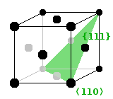
A plane within which block slip occurs (a slip plane) and the direction in which it occurs (the slip direction) are together referred to as a slip system. The first slip system to activate while the stress is ramped up is known as the principal slip system. The direction along which slip occurs is along the most densely packed lattice direction of the crystal, and the slip plane is the most densely packed plane containing the slip direction. For example, in the fcc structure, the face diagonals (110) of the unit cell are the most densely packed lattice orientation and therefore the slip direction, while the {111} plane is the most densely packed plane. As it also contains the slip direction, it is the slip plane of the principal slip system in this structure.
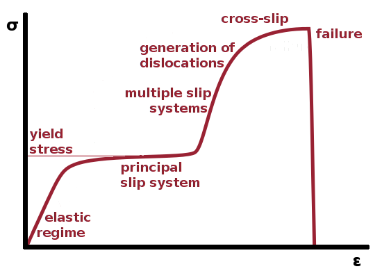
The stress-strain curve of single crystals is more complex than that of polycrystalline materials made up of multiple grains. When the material's yield stress is reached at the end of the elastic regime, the stress supplies sufficient energy to make dislocations mobile, leading to plastic deformation. At first, only the principal slip system is active, i.e. all dislocations move independently of one another. As they are all moving in the same direction, they never encounter each other and therefore do not interact. A small amount of additional stress causes a large additional strain in this part of the curve. During this process, dislocations are removed from the specimen when they emerge at the surface. This is known as work hardening, a method used to strengthen a material by applying stress in order to remove dislocations from it.
The next segment of the curve is steeper again, which means that the specimen will be more resistant to additional stress. In this regime, the yield stress of slip systems other than the principal one has been reached, so dislocations begin to move in multiple directions. If dislocations moving in different directions meet, they pin one another, and it will take more stress for them to continue moving. This makes the material stronger in this part of the curve.
This motion of dislocations along slip planes is known as glide. At even higher stress, the material softens again due to the formation of new dislocations. Just before failure, the energy supplied by the stress is sufficient for some dislocations to overcome obstacles by a mechanism known as cross slip.
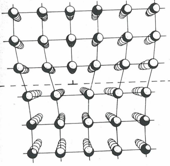
A dislocation is essentially the edge of a lattice plane which ends in the middle of the crystal. The local environment away from the edge is identical on both sides of the dislocation; the only distortion caused is around the edge because atoms have to adjust to the fact that there is less space to fill on one side of the dislocation than on the other. We can think of the dislocation separating the crystal into two halves (top and bottom in the Fig.) separated by the slip plane along which the dislocation is able to move. The dislocation is shown by an "inverted-T" symbol. It is important to realise that it is not the "inserted" lattice plane which is the defect but merely its edge as that is the only location where the structure deviates from that of an ideal crystal.
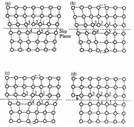
The Burgers circuit visualises the motion of a dislocation and demonstrates that no long-range motion of any atoms is needed for a dislocation to move through a crystal. The Fig. shows five labelled atoms in a plane surrounding the point where the dislocation intersects the display plane. Atom 2 is an atom at the edge of the dislocation. The atoms on this side of the slip plane are closer together than on the other. An individual step in the motion of a dislocation involves atom 2 moving closer to atom 3, which will require energy because of the repulsive part of the interatomic potential. This move leaves a large space to the right of atom 4, which will move into that space, recovering the energy expended previously by atom 2. The resulting configuration is identical to the original one, except that now atom 3 is the atom marking the edge of the dislocation. This process may continue until the dislocation hits the surface of the specimen, creating a step there. The Burgers vector, $\vec{b}$, represents the length and direction of that step. It is a property that characterises the dislocation, even before it actually reaches the surface.
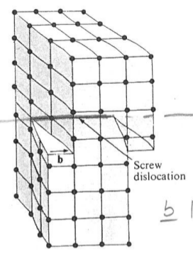
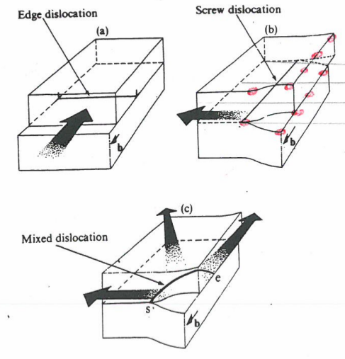
We can distinguish two dislocation types by the orientation of their Burgers vector. In edge dislocations, the Burgers vector is perpendicular to the dislocation axis, while in screw dislocations it is parallel. The slip plane always contains both the dislocation axis and the Burgers vector. This means axis and vector together define one specific plane in which an edge dislocation is able to move, while screw dislocations are able to move in different directions since axis and Burgers vector are parallel and therefore do not define a unique slip plane.
For a pure edge dislocation, the length of the Burgers vector is always equal to a lattice parameter. However, this doesn't have to be the case in general if the dislocation is moving in another direction. Edge and screw dislocations are just the end points of a series of dislocations with a continuous range of Burgers vector orientations. A mixed dislocation will have an edge component (Burgers vector parallel to dislocation) and a screw component (Burgers vector perpendicular).
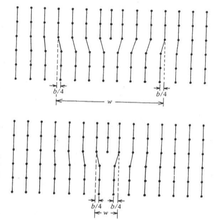
The energy stored in a dislocation is given by the dislocation width, i.e. the range over which the lattice is distorted either side of the dislocation. The larger the volume element is in which atoms are displaced from their equilibrium positions, the higher the potential energy of the crystal will be. Since the distortion fizzles out either side of the distortion, making it difficult to determine the limits of the distorted zone, the width of the dislocation is taken as the range over which atoms are displaced from their equilibrium position by at least a quarter of the Burgers vector.
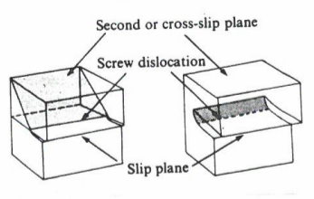
As we have seen, the motion of dislocations along different slip planes can restrict significantly their mobility at moderate stresses because dislocations gliding in different directions get in each other's way. If the applied stress is sufficient, screw dislocations have a way of overcoming this situation and keep moving. Because the Burgers vector and dislocation axis are parallel in the case of a screw dislocation, it is not restricted to movement within a single slip plane but can move between planes containing the same slip direction. This change of slip plane is known as cross slip.
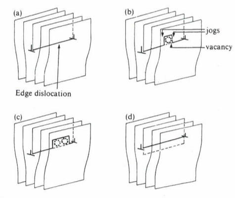
The cross slip mechanism isn't available to edge dislocations. However, edge dislocations can also overcome obstacles by an alternative mechanism assisted by vacancies. If a vacancy diffusing randomly through the crystal encounters a dislocation, it can become trapped there. This effectively means that an atom is removed from the edge of the dislocation. The resulting distortion makes it more likely for further vacancies to become trapped as well, taking away more atoms from the edge. If this continues happening, the dislocation effectively retracts by one lattice parameter perpendicular to the axis of the dislocation. This mechanism, which requires appreciable vacancy concentrations and therefore relatively high temperatures, is known as climb.
Elastic strain is proportional to the tensile stress causing it $$\epsilon=\frac{1}{E}\sigma\qquad,$$ where $E$ is the Young's modulus. Outside of a controlled tensile test, stresses may act on a specimen from several directions. Therefore, we can write the elastic equation for each direction separately: $$\epsilon_i=\frac{1}{E}\sigma_i\qquad\textrm{where}\qquad i=x,y,z\quad\textrm{(or 1,2,3)}\qquad.$$ Because of necking, there is also a (usually compressive) stress in the two directions perpendicular to the tensile axis:
$$\epsilon_j=-\frac{\nu}{E}\sigma_i\qquad\textrm{where}\qquad j\neq i=x,y,z\quad\textrm{(or 1,2,3)}\qquad,$$
where $\nu$ is Poisson's ratio. When the parallel and perpendicular stresses resulting from a stress along a single tensile axis are combined, we have: $$\epsilon_i=\frac{1}{E}(\sigma_i-\nu\sigma_j-\nu\sigma_k)\qquad(i,j,k~\textrm{cyclic})\qquad,$$ which is usually written with each subscript doubled: $$\epsilon_{ii}=\frac{1}{E}(\sigma_{ii}-\nu\sigma_{jj}-\nu\sigma_{kk})\qquad(i,j,k~\textrm{cyclic})$$ in order to distinguish these strains from shear strains, $$\gamma_{ij}=\frac{1}{G}\tau_{ij}\qquad,$$ which do not act along an axis but in a shear plane. Here $\gamma_{ij}$ refers to a component of shear strain in the direction of $j$ caused by a shear stress acting perpendicular to axis $i$.
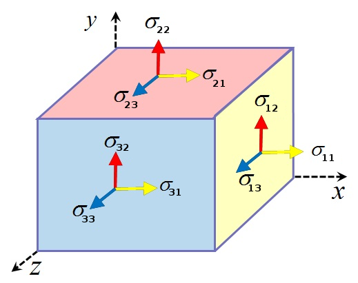
The tensile ($\sigma_{ii}$) and shear ($\tau_{ij}=\sigma_{ij}$) stress components can be combined into the 3×3 stress tensor, $\underline{\underline{\sigma}}$ which contains all stress components acting along any axes in a specimen. The stress cube (Fig.) illustrates this. Since its off-diagonal components are symmetric, it can be reduced to a six-component stress vector, $\vec\sigma$, containing the (diagonal) tensile components and the (off-diagonal) shear components of the tensor. It is linked to the strain vector, $\vec{\epsilon}$, by the stiffness matrix, $\mathbf{\Phi_e}$, which includes all the relevant moduli:
$$\vec{\epsilon}=\mathbf{\Phi_e}\vec{\sigma}= \left(\begin{array}{c}\epsilon_{11}\\\epsilon_{22}\\\epsilon_{33}\\\gamma_{12}\\\gamma_{23}\\\gamma_{31}\\\end{array}\right)= \left(\begin{array}{cccccc} 1/E&-\nu/E&-\nu/E&0&0&0\\ -\nu/E&1/E&-\nu/E&0&0&0\\ -\nu/E&-\nu/E&1/E&0&0&0\\ 0&0&0&1/G&0&0\\ 0&0&0&0&1/G&0\\ 0&0&0&0&0&1/G \end{array}\right) \left(\begin{array}{c}\sigma_{11}\\\sigma_{22}\\\sigma_{33}\\\sigma_{12}\\\sigma_{23}\\\sigma_{31}\\\end{array}\right)$$
As long as the strains are small, the volume change of a material under stress is:
$$\begin{eqnarray} \Delta V&=&(a+\Delta a)(b+\Delta b)(c+\Delta c)-abc\\ &=&\color{red}{\cancel{\color{black}{abc}}}+bc\Delta a+ac\Delta b+ab\Delta c+\color{purple}{\cancel{\color{black}{a\Delta b\Delta c}}^0}+\color{purple}{\cancel{\color{black}{b\Delta a\Delta c}}^0}+\color{purple}{\cancel{\color{black}{c\Delta a\Delta b}}^0}+\color{purple}{\cancel{\color{black}{\Delta a\Delta b\Delta c}}^0}-\color{red}{\cancel{\color{black}{abc}}}\qquad, \end{eqnarray}$$
where the first and last term cancel and the terms containing a product of two (small) strains can be neglected. The relative volume change of the material is then the sum of its linear strains:
$$\frac{\Delta V}{V}=\frac{bc\Delta a+ac\Delta b+ab\Delta c}{abc}=\frac{\Delta a}{a}+\frac{\Delta b}{b}+\frac{\Delta c}{c}=\epsilon_1+\epsilon_2+\epsilon_3\qquad,$$
and we can add up the tensile equations for the three spatial directions: $$\frac{\Delta V}{V}=\sum_i\epsilon_i=\frac{1-2\nu}{E}\sum_i\sigma_i\qquad.$$
As we've seen above, plastic strain is usually caused by the motion of dislocations. As long as the stress load isn't too high, i.e. no new dislocations are formed within the specimen, there will be no volume change during this process. According to the equation, if $\frac{\Delta V}{V}$ is to be zero, then Poisson's ratio must be $\nu=\frac{1}{2}$ for plastic deformation.
A small incremental strain ${\rm d}\epsilon_{11}$ will have an elastic component, $${\rm d}\epsilon^e_{11}=\frac{1}{E}({\rm d}\sigma_{11}-\nu{\rm d}\sigma_{22}-\nu{\rm d}\sigma_{33})\qquad,$$ which will be proportional to small incremental changes in stress. In addition, there may be a plastic component, $${\rm d}\epsilon^p_{11}={\rm d}\lambda\left(\sigma_{11}-\frac{1}{2}\sigma_{22}-\frac{1}{2}\sigma_{33}\right)\qquad,$$ which is proportional to the total stress load as this determines the mechanism by which dislocations can respond to the stress. Poisson's ratio is taken to be $\nu=\frac{1}{2}$ here, and the constant of proportionality is the plastic stiffness, ${\rm d}\lambda$, a material constant.
If the specimen is orientated in such a way that all shear stresses acting on its stress cube are zero and all tensile stresses are either at a maximum or a minimum, then the stresses acting on the faces of the stress cube are called principal stresses, $\sigma_i$ (as opposed to $\sigma_{ii}$, the general notation indicating both the axis along which a stress is acting and the axis on which it acts). Within this reference frame, it is possible to define the effective stress, $\overline{\sigma}$, and effective strain, $\overline{\epsilon}$, of the specimen: $$\overline{\sigma}=\sqrt{\frac{\sum_{ij}(\sigma_i-\sigma_j)^2}{2}} \quad\textrm{and}\quad \overline{\epsilon}=\sqrt{\frac{\sum_{ij}(\epsilon_i-\epsilon_j)^2}{2}}$$ The plastic stiffness is the ratio of the two: $${\rm d}\lambda=\frac{\overline{\epsilon}}{\overline{\sigma}}\qquad.$$
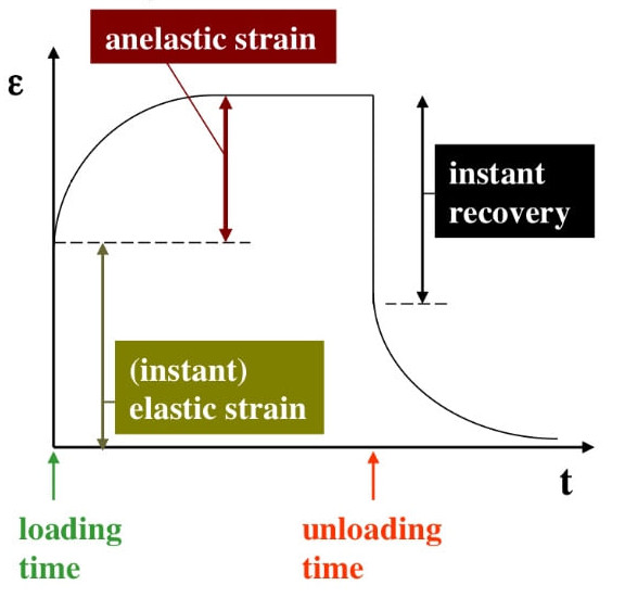
Anelasticity refers to a situation where a material shows a delayed response to a stress acting on it. After an instant elastic deformation, the strain continues to increase asymptotically towards a limiting value depending on the magnitude of the stress. When the stress is removed, the same behaviour is observed in reverse, i.e. an instant recovery is followed by a time-dependent relaxation towards the equilibrium shape in the absence of stresses. Anelastic strain occurs in materials which exhibit internal friction, i.e. a way for the structure to store energy by changes to the local structure. It is common in polymer systems, where the alignment of fibres can be adjusted under stress.
Having established some of the different types of strain which occur in solid materials and the role dislocations play in the response of materials to stresses, we will next see how we can measure strain by diffraction of x-rays or neutrons.