
Any crystal structure features lattice planes as a consequence of the translational symmetry of the periodic lattice. A lattice plane is any cross section across the structure which contains atoms at regular intervals. The most obvious lattice planes are those which coincide with the faces or diagonal planes of the unit cell; such planes are the ones with the highest density of atoms.
Waves whose wavelength is comparable to the lattice spacing (e.g. x-rays, neutrons, electrons,...) are diffracted by a stack of lattice planes. A simple interpretation of the diffraction mechanism treats each lattice plane as a semi-transparent mirror. A ray is either subject to specular reflection or passes through the lattice plane, in which case it may be reflected off the next, parallel, plane, and so on. This interpretation neglects the fact that lattice planes are made of atoms, and that the electron density is not equally distributed within a plane. However, it provides a simple geometrical picture which does give correct results.
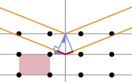
The Figure shows a primitive rectangular crystal with one unit cell highlighted. One set of parallel lattice planes is indicated (grey), and a normal to the lattice plane is shown in green. A ray from an x-ray beam is reflected at the top lattice plane; as with any specular reflection, the incident and reflected angles are the same. A second ray passes through the top lattice plane and is reflected at the second lattice plane. The ray is chosen such that it hits that lattice plane at its intersection with the same lattice normal as the first ray (in practice, this is achieved using optical slits). Since the two lattice planes and the two incoming rays are parallel, respectively, the reflected rays are also parallel.
The ray reflected off the second plane has a longer distance to travel before reflection occurs than the first, as indicated by the purple line segment shown. Because lattice planes and lattice normal are at right angles, the angle of incidence is equal to the angle between the lattice normal and the wave front (both indicated in solid green). Thus the extra travel distance before reflection is $$d\sin{\theta}\qquad,$$ where $d$ is the lattice spacing (distance between lattice planes) and $\theta$ is the angle of incidence. Since the whole diagram is symmetrical about the lattice normal, the same extra travel distance also occurs on the right hand side, i.e. after reflection.
Given that the rays are waves, the extra travel distance causes a shift of phase of the second ray relative to the first; in general, they will not interfere entirely constructively. For constructive interference to occur, the additional travel distance must be an integer multiple of the wavelength to ensure both rays remain in phase. This is Braggs' law:
$$2d\sin{\theta}=n\lambda\qquad.$$
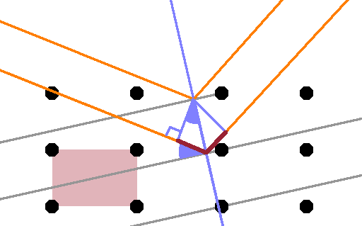
Of course the lattice planes are just a construct that enables us to use classical optics to predict what kind of diffraction occurs. The same crystal, with the same orientation relative to the x-ray beam, has many other sets of lattice planes such as the one shown in this Figure. The planes shown here cut through three unit cells horizontally for each translation by one cell vertically. The incident angle on this set of planes is steeper, the extra travel distance longer, and although the reflection will be weaker as the rays have to penetrate deeper into the crystal, we can expect a peak from this (and any other) lattice plane, too.
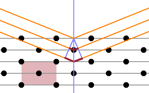
If the crystal has a centred unit cell rather than a primitive one, an additional lattice plane is inserted between each pair of planes - compare this Figure with the first at the top of this page. However, the atoms in this lattice plane aren't in the same places as in the original planes, so the lattice distance $d$, which is the distance between identical planes, remains the same. Thus, if the rays reflected at the original two planes are in phase, the ones reflected at the interspersed 'centred' planes are exactly anti-phase, leading to destructive interference, and no Bragg reflection is recorded.
This is known as a systematic absence - although the reflection is consistent with Braggs' law, only every other order ($n$) actually produces a peak.
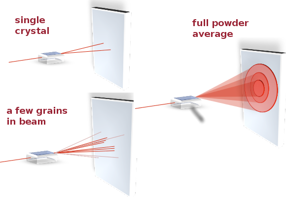
By varying the incident angle and exposing as many different lattice planes as possible, a full diffractogram can be obtained. By analysing the peak positions and, where applicable, systematic absences, the lattice parameters and space group of the crystal can be determined. In practice, powder diffractograms are most useful when trying to identify a material by comparison with a database of known crystal structures because they provide the best statistics and include reflections from all planes. On the other hand, in single-crystal diffraction, a macroscopic single crystal is carefully rotated about several axes between exposures so that each frame provides information about a single set of lattice planes. This removes ambiguities in the interpretation of the data and is more likely to result in the correct indexing (see below for Miller indices) of all Bragg peaks in a new material or mineral for which no powder diffractogram has been recorded yet.
Braggs' law predicts the positions of the diffraction peaks as a function of the diffraction angle, $2\theta$, but treating the lattice planes as semi-transparent mirrors is of course a gross misrepresentation of the scattering process. Both X-rays and electron beams scatter by interaction with electrons in the atoms of the crystal, while neutrons interact either with the atomic nuclei or magnetic moments associated with the atoms. In either case, there is no specular reflection, and the lattice planes are merely a construct to help us visualise the structure.
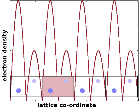
As the electrons in the structure cause diffraction, the distribution of the electrons must be crucial to the shape of the diffraction pattern. The common characteristic of crystal lattices is their periodic structure. Therefore, the electron density, $n$, is a periodic function. The Figure shows four repeats of a unit cell with two atoms and a crude schematic of the resulting electron density distribution.
A translation by an integer multiple of the lattice parameters, represented by the vector $$\vec{T}=t_1\vec{a}+t_2\vec{b}+t_3\vec{c}$$ therefore makes no difference to the electron density $n$: $$n(\vec{r}+\vec{T})=n(\vec{r})$$ where $\vec{a}$, $\vec{b}$, $\vec{c}$ are the lattice vectors, $t_{1,2,3}$ the number of unit cells the position is shifted in each direction, and $\vec{r}$ are the co-ordinates of the original lattice point before the translation.
In a one-dimensional crystal, the electron density is simply a function of the spatial co-ordinate $n(x)$, with a periodicity of length $a$. As a periodic function, we can expand it into a Fourier series of sine and cosine waves to obtain a form that can be treated analytically: $$n(x)=n_0+\sum_{m\gt 0}{\left(c_m\cos{\frac{2\pi mx}{a}}+s_m\sin{\frac{2\pi mx}{a}}\right)}$$ where the $c_m$ and $s_m$ are the Fourier coefficients of the individual harmonics of order $m$. The factor $\frac{2\pi}{a}$ arises owing to the need to fit a full period ($2\pi$) to the length of the lattice parameter $a$.
Using Euler's relationship, we can replace the sines and cosines by a complex exponential: $$n(x)=\sum_{m=-\infty}^{\infty}{n_m{\rm e}^{{\rm i}\frac{2\pi mx}{a}}}$$ with complex Fourier coefficients $n_m$.
However, not all of these coefficients are independent because the electron density $n(x)$ must be a real function to make physical sense. It will be real if the complex conjugates of the Fourier coefficients with negative indices are the same as the coefficients with the corresponding positive coefficients, i.e. $$n^{\ast}_{-m}=n_m\qquad.$$
In three dimensions, $n(x)$ becomes $n(\vec{r})$, where $\vec{r}$ is the vector from the lattice origin to a lattice point, giving its co-ordinates along all three axes. The complex exponential thus contains a scalar product: $$n(\vec{r})=\sum_{\vec{G}}n_{\vec{G}}{\rm e}^{{\rm i}\vec{G}\vec{r}}$$ where $\vec{G}$ plays the same role as the factor $\frac{2\pi m}{a}$ did in the one-dimensional case. As the argument of the exponential function must be dimensionless, the three components of $\vec{G}$ must be in units of ${\rm m}^{-1}$. The vector $\vec{G}$ is called a reciprocal lattice vector , $\vec{G}$ in ${\rm m}^{-1}$ and it is the vector from the origin of the reciprocal lattice of the crystal to a reciprocal lattice point of its particular crystal structure.
As in the direct lattice, the reciprocal lattice is spanned by unit vectors. These relate to the unit vectors of the corresponding direct lattice: $$\vec{b}_i=2\pi\frac{\vec{a}_j\times\vec{a}_k}{\vec{a}_i\cdot\vec{a}_j\times\vec{a}_k}$$ where $\vec{a}_{i,j,k}$ and $\vec{b}_{i,j,k}$ are the unit vectors of the direct and reciprocal lattice, respectively.
Positions within the unit cell are specified in terms of translations along the three lattice vectors, e.g. the atoms in a bcc unit cell are at (0,0,0) and (½,½,½).
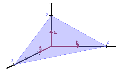
Lattice planes are indexed by their intercepts of the coordinate axes. Lattice planes are identified by their Miller indices, (h k l). To obtain the indices of a lattice plane, the reciprocals of the intercepts are taken, and the set of smallest integers giving the same ratio between them is determined. These are the Miller indices for the lattice plane, usually represented as (h k l).
| intercepts: | a=3 | b=2 | c=2 |
| reciprocals: | 1/3 | ½ | ½ |
| indices: | h=2 | k=3 | l=3 |
The table shows the calculation for the lattice plane shown in the diagram. The use of the reciprocals for the indices may seem unintuitive at this point. We will see that measuring crystal structures by diffraction maps reciprocal space rather than real space. This is the reason for the conventional use of reciprocal Miller indices.
The same formalism is used to describe sets of equivalent lattice planes {h k l} (in curly braces) and lattice directions [u v w] (in square brackets), i.e. vectors aligned normal to a given lattice plane.
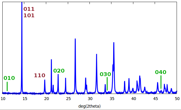
The figure shows a diffractogram, i.e. the x-rays counted as a function of diffraction angle ($2\theta$). Some of the Bragg peaks have been indexed, i.e. the Miller indices for the lattice planes responsible for these reflections have been assigned.
In this particular case, the $\{0kl\}$ and $\{h0l\}$ reflections contribute to the same peak, while $\{hk0\}$ reflections are separate. This means the symmetry of the crystal is such that the $a$ and $b$ lattice directions are equivalent. Only every other homologous peak of the $\{0k0\}$ family seems to be present - a case of systematic absence.
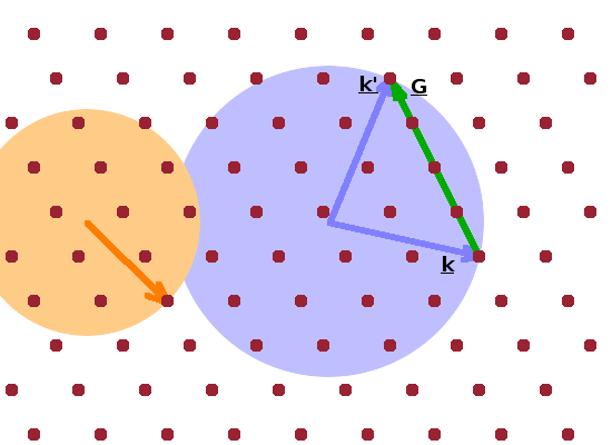
The Ewald construction is often used to visualise the conditions in the reciprocal lattice under which a Bragg reflection occurs. For the construction, a wave vector, $\vec{k}$, is drawn such that its tip coincides with a lattice point. The vector starts from an arbitrary origin, i.e. not necessarily a lattice point. It represents an incident photon or neutron. Next, a circle with radius $k$ is drawn around the origin (shown in blue in the Figure). The tip of the wave vector will therefore be on the circle. If there is another lattice point located exactly on the circle, then a scattering event will result in positive interference. The difference vector between the two wave vectors from the origin to each of the two lattice points on the circle is the momentum transfer, $\vec{q}$: $$\vec{q}={\vec{k}\,}'-\vec{k}\qquad(=\vec{G})$$ It corresponds to a reciprocal lattice vector, $\vec{G}$ since both points are part of the same lattice plane.
As the orange circle demonstrates, the diffraction condition isn't fulfilled for every wave vector: The orange wave vector ends on a circle which contains no other lattice points (although there is a near miss at the top right), so the ray will not interfere constructively.
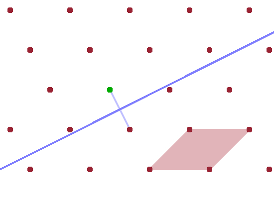
Another way of visualising the reflection condition is the construct of the Brillouin zone. It is used more widely in condensed matter physics as it represents the interaction of any kind of wave with the crystal lattice, including diffracting x-rays and neutrons but also standing waves of delocalised electrons in metals and sound waves travelling through the crystal. We will first establish the geometrical construction of the (first) Brillouin zone and then use it to establish the diffraction condition. Brillouin zones will feature again in later parts of this course such as those on the electronic structure of solids and on phonons.
Constructing the Brillouin zone of a particular reciprocal lattice involves the following steps:
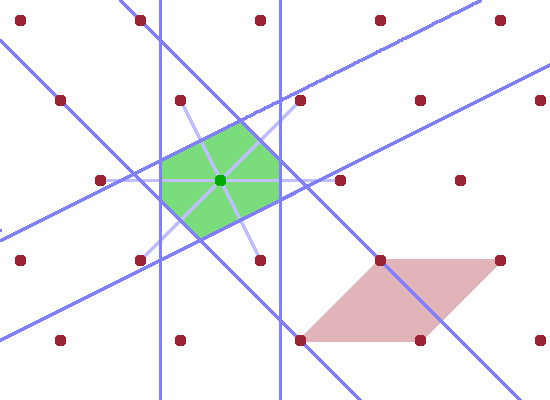
The resulting, somewhat irregular, polygon is the first Brillouin zone. The significance of the first Brillouin zone is that it contains the wave vectors of all waves that can travel within the crystal lattice. Waves with wave vectors outside this range can be represented by adding a reciprocal lattice vector $G$ to a wave that falls within the Brillouin zone.
The final Figure demonstrates the role of the Brillouin zone in terms of scattering. A wave vector $\vec{k}$ starting at the lattice point in the centre of the unit cell and ending anywhere on the zone boundary is reflected at the zone boundary (incident angle equals reflected angle as usual). The resulting elastically scattered wave vector $\vec{k}'$ is shifted such that it also starts at the lattice point in the centre. This is the common model for a scattering process: an incident ray hits an atom and is deflected by it. Since, by definition, no energy is transferred in an elastic scattering process, $\vec{k}$ and $\vec{k}'$ have the same length, and the shifted instance of $\vec{k}'$ therefore also ends at a zone boundary. The difference vector $$\vec{q}=\vec{k}'-\vec{k}$$ is the momentum transfer, $\vec{q}$. By shifting $\vec{q}$ also in such a way that it begins at the lattice point at the centre of the Brillouin zone, it becomes clear that $\vec{q}$ is equivalent to a reciprocal lattice vector, $\vec{G}$, i.e. a vector connecting two reciprocal lattice points. Therefore, the diffraction condition $$\vec{k}'-\vec{k}=\vec{G}$$ holds. This applies to any wave vector which reaches a zone boundary from the centre of the Brillouin zone.
This concludes the section on crystallography and diffraction. We will return to this topic later (in the Structure Determination module) when dealing with crystal defects and strain. But first, we'll be looking at the lattice dynamics of solid materials.